Optical Terms and Principles
What are the Optical Tooling instruments?
Fundamentally, these are transits, levels, and alignment telescopes. Let's take a very quick look at each.
 The alignment telescope is "just" a telescope, with a very straight line of sight. It must be mounted in some sort of base to hold it horizontally or vertically (we have all sorts of bases). Sometimes it has built-in micrometers for making measurements, but not always. Sometimes it is really just a telescope!
 One step "up" from an alignment telescope is a level. The most important thing about a level is that it is a telescope on a rotating base, which allows the telescope to rotate back and forth in the azimuth (horizontal) direction only. Further, this type of instrument is optimized for easy and quick adjustment of the telescope so that the line of sight becomes perfectly level.
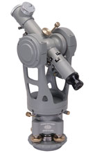 Everyone has seen a transit-type instrument at some point. Surveyors use them outside to make measurements on roads and buildings. The most important thing about a transit is that it has a telescope on a gimballing mechanism, so it can rotate back and forth horizontally (azimuth direction), but it can also rotate up and down (elevation direction).
However, it is worth explaining the general difference between our transits and those used by surveyors. Optical Tooling transits have a number of modifications to make them deadly accurate when shooting over distances which, to a surveyor, would seem short (less than a hundred feet). For example, our telescopes have an extremely straight line of sight. This means that as you focus from near (2" from the objective) to far, you are "moving" in a very, very straight line. Also, the vertical and horizontal axes of our transits meet at exactly the same point in space, along with the transit's line of sight. Not only that, but all of these lines and axes are at 90° to each other (mutually orthogonal). This is one of the fundamental characteristics of our instruments that allows us to evaluate geometric relationships of other things. Finally, our 76-RH transit has an infinity-focused telescope mounted in the horizontal cross-axis around which the main telescope turns. We'll see why this is, later in our discussion.
Of course, there are a lot of other instruments and accessories (collimators, mirrors, stands, bases, targets, scales, and so on), but the three basic types of instruments above are the workhorses of Optical Tooling.
 The telescope of each Optical Tooling instrument contains a reticle - or crosshair - which defines the center of the line of sight for that telescope. When you look into a telescope, you see the reticle "superimposed" upon a distant image - whatever image you have the telescope focused on. The reticle is split into two different halves; one half has a single "wire", the other has a double "wire". This configuration makes it much easier to visually align the reticle with other images (ex., optical targets and reticle images reflected from mirrors). [Interesting tidbit: in the old days, we used to use threads from black widow spider egg nests to make our crosshairs. No lie!]
From an optical standpoint, light rays coming from an "infinite distance" are all parallel to each other, or collimated (see the next topic).
Parallel light rays are said to be "collimated." When a telescope is "focused at infinity", it means that only parallel light rays which are entering the telescope will be clearly seen by an observer looking into the eyepiece. Remember that for our purposes, objects that are farther than about 100′ will have light rays which are sufficiently parallel to be in focus. When the telescope is focused in this manner, images from closer than "infinity" are not viewable (out of focus).
And did you know that a telescope could work backwards? No, we don't mean looking into the big end so that your coworkers look like ants. We mean that if you put a light near the eyepiece, you can shine light rays back out the big (objective) end. This means that if you illuminate the reticle of an instrument which is focused at infinity, it projects collimated light rays out the front.
"So what?", you might say. Well, when these collimated rays are viewed with a second telescope which is also set at infinity focus, you can see an image of the illuminated reticle of the first telescope. If the second telescope is aimed precisely at the "incoming reticle image", you can exactly superimpose the first (projecting) telescope's reticle image over the actual reticle of the second telescope, and the lines of sight of the two telescopes are established as parallel.
Remember that parallel doesn't mean that the lines of sight travel down the exact same path in space (if they did, they would be collinear). The lines of sight are exactly parallel (which is very useful for transferring reference lines) but they are not collinear - they are more like railroad tracks. [Tidbit: if you want to make the lines of sight collinear, you can do that too. All you need to do it is read on…]
 Well, now that you have made the lines of sight of two telescopes parallel by collimating them, you can take it one step further if you'd like. Picture two telescopes pointing at each other, both focused at infinity, and collimated. As we've discussed, if you look into either telescope, you should see two reticle images. One is in the near telescope (the one you're looking into), and the other is in the far telescope. However, if you were to focus both telescopes, say, on a piece of paper held up about halfway between the instruments, the reticles would no longer be superimposed - unless you were incredibly lucky, that is. Remember that the lines of sight are parallel but not necessarily "superimposed" upon each other. However, there is a procedure that you can use to superimpose the reticles at this near shot while the instruments are still collimated at infinity. (We call it a "near shot" because the telescopes are focused closer than infinity.) After performing this procedure, the lines of sight become collinear. They're not just parallel any more - they actually exist along the exact same line in space.
Why would you do this? Well, most of the time the transfer of a reference line requires only collimation. But sometimes, if you can't see both sides of an object, or if you are trying to transfer a particular horizontal or vertical plane in an area where visibility is restricted, the technique of collineation can be just the thing to use.
Remember what we said about a telescope being used backwards? Another thing that you can do when you illuminate the reticle is to put a telescope in projection mode, which allows you to project an image of the reticle onto some surface at which the telescope is pointed. This time, you don't work at infinity focus, but instead you must focus at the surface on which you want the reticle image to appear. So once you establish the desired reference line, turn the ambient lighting down a little and project an image of the crosshairs on the surface - this will give you a clear visual indicator of your reference line for use in building, positioning, estimating, etc.
OK, this was a trick one that you already know. A reflection is just what you see when you look into a mirror. But this brings us to our next definition…
Suppose you were to look through a telescope at a mirror. If you pointed the telescope directly at the mirror, so that the line of sight was perpendiular (90°) to the mirror, you would see the end of your own telescope. Now suppose you put a target on the end of the telescope itself, like a nice black crosshair painted on the objective lens (don't actually do this - we have special targets for you to use). Since you can see the objective lens of your own telescope (and the nice target on it) in the mirror, you would be able to position your own instrument's internal reticle over that reflected image. This would give you a very accurate way to make sure that your telescope is perpendicular to the mirror.
"Then what?", you might say. Well, suppose that the mirror is on the end of a rotating shaft from which you need to extend an axial reference line. Not so strange after all, is it? Especially when you remember that you can do other interesting things with the mirror, like turning the shaft on which it is mounted and observing the target's reflection move around, letting you know whether the mirror is truly perpendicular to the center of rotation of the shaft or not.
When you really want the ultimate accuracy in angular control, autocollimation is the technique to use. Autocollimation is more accurate than autoreflection, but often, autoreflection is performed first, making autocollimation easier to achieve.
Remember that in autoreflection, the line of sight is aimed at the reflection of a target which is mounted on the objective end of the telescope through which the observer is looking. But in autocollimation, the line of sight is aimed at a reflection of the crosshairs of the telescope itself.
Remember again what we've said about using a telescope "backwards". To autocollimate an instrument, it is necessary to direct a small amount of light on the reticle. This light will then shine out the front end of the telescope. Before you start drilling holes in your telescope to shine a flashlight in there, we should tell you that we make special things to light up your telescope's reticle. Anyway, when the reticle is lit up and the telescope is focused at infinity, parallel light rays will go out the objective end. Then, if you then look through that same telescope, since it is pointed at a mirror (just like with autoreflection), the parallel light rays bounce back from the mirror, and you can see a reflection of your own crosshairs in your own instrument. Stay with us - this is not nearly as difficult as those time-travel paradoxes.
 This is what the process of autocollimation looks like when looking through the telescope. After the reflected image is lined up exactly on the original reticle (in the illustration, blue lines directly over black lines), the telescope is precisely perpendicular to the mirror that is producing the reflection.
When the mirror (or the instrument) is adjusted so that the reflection of the reticle falls exactly on the original reticle itself, the telescope has been very accurately positioned perpendicular to the mirror.
"Why do this?", you ask. Well, as it turns out, this is an extremely accurate way to establish a right angle with respect to an optical reference line. Our transits have an infinity-focused telescope on the cross-axis, which happens to be just perfect for use in autocollimation.
Measuring with Micrometers
"So far", you might say, "we haven't actually measured anything". Of course, you are right. How do we measure things with optical tooling? That's where micrometers and scales come into play.
Suppose that you are suspicious that a large table is not level. Not being the type that is normally paranoid, you want to take a profile of the table to see for sure. You have set up an optical instrument called a "level" overlooking the table. The telescope of the level has been easily adjusted so that the line of sight is perpendicular to gravity, and the line of sight sweeps across the table, in a plane which is pretty much parallel to the table top. Now you want to take some measurements. So you pick up an Optical Tooling scale and scale holder, and set it up somewhere on the table. Optical Tooling scales are just like the wooden rulers that you used in school, except that they are not wooden, and they are a lot more accurate. The scale is oriented so that it sticks straight up vertically from the flat table. Now you look through the level's telescope at the scale, and you notice that the crosshairs are right in between the 3.2 and 3.3 markers. Hmmm...
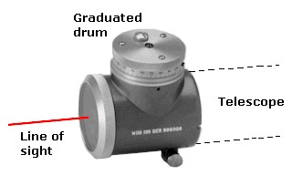 Don't worry. There is a micrometer on the front of your telescope. This is an optical micrometer which contains a block of glass that when rotated, moves the incoming image up and down by known amounts. It's one of those really cool things from physics. Anyway, all you have to do is turn the graduated drum on the micrometer, which offsets the image and makes it appear to move up and down, until the crosshairs appear to be right in line with the 3.2 mark on the scale. Then you look at the graduated drum on the micrometer to see how much you moved the image. If you moved it, say, 0.036", then you know that the line of sight is precisely 3.2 (as read from the scale) + 0.036 (as read from the micrometer) = 3.236" above the table. Cool!
Now move the scale somewhere else on the table and take another reading. This time, using the same process, you take a reading of 3.276", which you can immediately calculate is a point 0.040" below the first reading (yes, below, because the scale had to go down by 0.040" to get a reading of 3.276 - the line of sight stayed level). You can take any number of additional points to determine whether the table is level - or whether it's even flat, which is a different question. This process is essentially how all measurements are made using Optical Tooling instruments, whether they're made up, down, or sideways.
