Optical Tooling Techniques
We are nothing if not practical!
Let's take a closer look at the practical side of Optical Tooling. We'll go over some examples of Optical Tooling principles at work and what you can do with the instrumentation. As you read on, remember one thing - Optical Tooling is a very flexible system. The examples listed below are only a few of the things that are possible using the Optical Tooling system - you are limited only by your own imagination. Also, remember that because of this flexibility, you can often use instruments other than those shown in the illustrations below, to accomplish the same goals. (For example, a model 76 transit with a coordinate optical micrometer can often be substituted for a model 2022 alignment telescope.)
Calibration of Laboratory optics
This is a good example of using an alignment telescope to hold an absolute reference line. Alignment telescopes are used to establish and maintain principal reference lines of sight (LOS). In addition, they provide the important functions of autoreflection, collimation, and autocollimation. Brunson alignment telescopes are made of heavy-walled, heat-treated, special alloy steel tubing, concentrically ground inside and out to extremely close tolerances. The optical systems are precisely installed to provide accuracy on your projects.
In the illustration below, a model 2062 Alignment Telescope is autocollimated on the surface of a multi-sided mirror. The mirror is mounted on a precision angle-turning device, such as an Ultradex™. Since the 2062 is autocollimated on the mirror, we know that it is looking into the mirror at exactly a 90 degree angle. Now, the mirror is turned by 90 degrees using the Ultradex mount. The 2062 holds the reference line of sight (LOS) while this is done. Then, in its new position (known to be exactly 90 degrees from the prior position by virtue of the Ultradex), the autocollimated image of the alignment telescope's reticle is again checked. Any deviation from the centerline represents an error in the mirror. Note that this example only involves holding a reference line of sight. The 2062 is well-suited to applications that do not require measurements or micrometer readings.
Holding a reference line of sight for calibration of laboratory equipment
Generating a perfect right angle (to make parallel lines)
The sketch below illustrates how a model 2062 can be used to hold a reference line of sight in a multi-instrument setup. The 2062 in this instance serves as a reference instrument for positioning a transit using the principle of collimation. A transit is positioned perpendicular to the alignment telescope by collimating the transit's cross-axis telescope on the 2062's line of sight. Each time you move the transit laterally to a new position along the 2062's line of sight, you can check the transit against that line of sight. By referring back to this "absolute" reference line each time you move the transit, you eliminate the need to "leap frog" from one position to the other (which would tend to accumulate error each time you move).
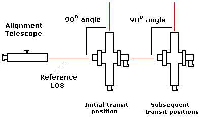
The alignment telescope holds a reference line of sight for a transit when turning a 90° angle, allowing you to establish a number of parallel lines which are all perpendicular to the original reference line of sight.
Evaluating straightness of bores (Comparing machine components to a centerline)
Optical tooling has some very unique ways to evaluate straightness of components; i.e., to determine whether they are all on a common centerline. The model 2022 Alignment Telescope is similar to the 2062, but has two micrometers which allow it to perform precise measurements (horizontally and vertically), perpendicular to the line of sight. The telescope has built-in provisions for keeping the line of sight straight within a focusing range of 2" to infinity, allowing the instrument to be located in the tightest of setups. The 2022 is also equipped for autocollimation and autoreflection if required.
The basic idea is to position the instrument so that its line of sight is collinear with the desired centerline. Sometimes the instrument is positioned using known master reference targets. Sometimes this is done by autocollimating to target/mirror combination which gives not only lateral information but directional information as well (perpendicular to the mirror). Sometimes this is done by lining up on the center points of the first and last machine components, or the near and far ends of a bore.
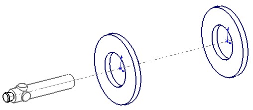
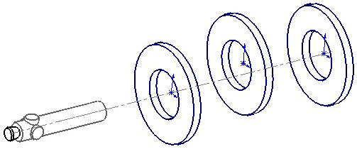
The line of sight of the telescope is made to pass through targets on each end of a bore, defining a reference centerline.
The cool thing about optical tooling is that it is just about foolproof. Let's say that you look down a bore to the very end. You can position a target down there (called a "bore target"). This is a special target that allows you to center an optical target right in the middle of the bore. Axial legs hold the target in place and a dial indicator on a sweep arm allows centering of the target in the bore. This defines the far end of the bore (represented by the disk at right in the illustration.) You can also position another such target at the near end (left disk in the illustration). By using any number of adjustable bases available for our alignment telescopes, you can position the instrument so that both targets (near and far) appear to be in the center of the telescope's image. This means that the instrument's line of sight is now collinear with the targets placed at the centers of the near and far ends of the bore.
Now that you have a reference centerline defined, it is easy to measure the straightness of the bore by moving one or both of the bore targets to various positions along the bore. As long as you don't move the instrument which has been positioned on the centerline, you can measure the relationship of any other target position to the reference centerline. Remember that the 2022 has built-in horizontal and vertical micrometers, which allows a direct reading of any target inside the bore. If a gravity reference is required, a model 187-S stride vial can be set on the alignment telescope to establish a level line of sight.
Measuring a new target in an intermediate position may show a deviation in the straightness of the bore, as illustrated above. The micrometers on the alignment telescope will quantify the error.
This same alignment principle is used when positioning new machine components on a line which is defined by existing components. The targeting may vary slightly, depending upon the requirements of the job, but the principle is identical to the measurement of a bore.
Alignment of bearing journals
Measuring bearing alignment in an engine block and evaluating for straightness is another easy task with an instrument like the 2022. Notice that the application is very similar to a bore alignment (described above). Again, the instrument is positioned so that the line of sight is coincident with some known or desired reference. This time, a target placed at various bearing supports in the engine block and measurements relative to the instrument's straight line of sight are made. Horizontal and vertical profiles can be generated for each bearing housing to determine alignment. We supply a large variety of targeting to facilitate many different types of alignments. Chances are, we've seen something like your application before, and have a target that is just right.
Bearing alignment in an engine block
Extruder alignment
The 2022 Alignment Telescope is also great for measuring the alignment of an extruder tube relative to a gear box housing. To accomplish this, targets are mounted in the gear box so that the 2022 can be positioned exactly on the gear box's critical line. Once the 2022 has been positioned, it optically represents the gear box's centerline, and measurements can be taken on work targets (or one work target which is moved to several different positions) in the extruder tube to determine if the tube is in alignment with the gear box. Deviations from the centerline can be quantified and technicians can be told exactly how much to move machine components to bring everything back into alignment. In fact, an instrument operator can observe the progress while adjustments to the machinery are being made. Alignments like this are crucial for preventing damage to a gear box.
Leveling a machine bed or foundation
The Brunson model 545-190 level, also referred to as a precision sight level, builds upon the construction and design principles of the alignment telescopes. Precision sight levels can perform many of the same operations as both the 2062 and 2022 alignment telescopes. However, they are optimized for leveling operations, having the additional ability to sweep a horizontal plane and perform precision leveling operations using a built-in split-bubble vial.
In this example, a precision sight level is mounted on a stable stand, and rough-leveled using the attached bull's eye vial. Then, the main leveling screw is moved so that the telescope is brought exactly level. This is determined by watching a magnified split-bubble image of a very precise vial mounted on the side of the instrument. This fine-threaded leveling screw makes it very easy to bring the telescope into a level position within 1 arcsecond.
Leveling a machine bed or foundation
Once the instrument is established as level, scales are mounted in various positions on the machine bed or foundation. It is equally easy to use one scale and move it around to the positions of interest. Readings to the nearest 0.001" or 0.03 mm are taken at each scale position using the precision sight level's micrometer as a vernier. Scale readings from the different positions are then compared to determine whether the platform is out of level, in what direction is it out of level, and by how much. Again, adjustments may be made to the bed while someone observes the bed's movement by watching the scales through the precision level's telescope in order to give immediate feedback to the person doing the adjustment. Once the bed has been nominally leveled, a thorough evaluation may be made to see if the bed is flat, or whether there is any undesired sag or curvature.
Leveling a roll
Precision sight levels may be used to provide horizontal references for just about anything. Similar to the example which describes leveling a machine bed, a precision sight level can be mounted on a stable stand so that it has a "clear line of sight" at both ends of a roll. This roll might be in a paper mill, printing press, metals mill, plastic mill, or plastic film rolling mill.
Sometimes the only way to see both ends of a roll is to look almost straight down the roll from the end. Even this situation is easily handled by virtue of the precision horizontal reference plane created by the level. This illustration shows a plan view of a level which can be rotated in order to view each end of a roll. A vertical optical tooling scale is mounted on the roll (either on the bearings, or preferably, on the surface of the roll itself). Then the level and associated optical micrometer are used to take readings from scales on each end of the roll. But how do you know that the scale is actually vertical? Any of our optical tooling scales can be outfitted with a scale level, which is a bull's eye vial made with a special mount in order to help you put your scale in a horizontal or vertical orientation.
Leveling a roll (view from above)
Making Machine Components Vertical
Making things vertical is almost as easy as making them horizontal. To do this job, however, you have to use a transit rather than a level. A procedure called "precision plumbing" can be performed on any transit which has been mounted on a stable stand or other foundation. This procedure allows the operator to ensure that the vertical spindle of the transit is perfectly vertical - as in "exactly parallel to gravity", not just pointing generally "up and down". After a transit has been precision-plumbed, we know that the telescope will rotate through a vertical plane, regardless of what azimuth (horizontal) direction that plane is oriented.
Plumbing machine tool columns
We then must bring the transit into a position where it is nominally parallel to the surface that we're trying to measure. We do this using a simple procedure called "bucking in". The illustration shows the use of a transit to plumb a machine tool column (or any vertical surface). In this application, the transit sweeps a vertical plane through scales that are affixed horizontally to the machine column. The measurements are relative to this vertical optical reference plane, and we will quickly know whether the machine is vertical or not, and how much out of plumb it is. That is, if all of the scales give us exactly the same reading, we know that the machine surface is parallel to our vertical plane. But if they're not, we can tell how much the surface is leaning one way or the other, and in fact whether the surface is flat or curved. The observed measurements can be used to plumb the machine component.
Making rolls (or other components) parallel
This is where things get even more interesting. Not as in "difficult", but actually just more interesting. Let's say that you need to evaluate a number of machine components to make sure they are all parallel (like rolls in a rolling mill). One way to approach the job would be like this:
- Establish a reference line running parallel to the entire machine (so that ideally, all rollers should be perpendicular to this line).
- Set up an instrument to turn a precise right angle from this reference line.
- Measure how parallel each roll is, using the instrument at right angles to the reference line.
Let's take a close look at each of these steps.
There are several ways to establish the reference line which runs parallel to the entire machine, but let's use a somewhat typical situation. Suppose that an "offset centerline" is marked by floor monuments near the machine. This is a line which is parallel to the machine centerline, which was established by floor markers at some time in the past. Picture a vertical plane rising up through these floor markers. We can set up a model 76-RH transit so that it is directly in line with this vertical plane, and pointing in the direction established by the floor markers. We'll call this instrument "A". When this is done, we have one transit whose line of sight can be used as the reference because it has been set exactly parallel to the machine centerline. We set the focus of this instrument at infinity and turn on the reticle illumination light. Why do we do this? Stay tuned…..
Next, we set up another model 76-RH transit somewhere near one of the rolls that we want to align. We'll call this one "B". Remember that the 76-RH has a horizontal cross-axis telescope permanently focused at infinity, which is mounted exactly perpendicular to the main telescope. When we point the main telescope of instrument B toward the rolls, its cross telescope will be pointing back at transit A. Since we focused A's telescope at infinity and illuminated its reticle, we can collimate B's cross-telescope on the reticle in A's main telescope. This alignment process causes the main telescope of B to become exactly perpendicular to the main telescope of A. Accordingly, the main telescope of instrument B can now sweep a plane which is perpendicular to the machine centerline.
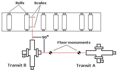
View from above: A and B work together to determine how far each roll
is from being perfectly perpendicular to the machine's centerline.
We then hold an optical tooling scale on the side of the roll (near the end), oriented horizontally. Scale bubble levels help us to know that the scale is actually horizontal and that it is placed properly on the roll. We take a measurement on this scale using the micrometer on instrument B. Then we move the scale to the other end of the roll and repeat the process. Taking measurements on each end of the roll will reveal the degree to which the roll is not parallel to B's line of sight. We know that the roll must be parallel to B's line of sight in order to be perpendicular to the machine centerline.
When we are finished with this roll, we simply move transit B over to the next roll. Sometimes more than one roll can be measured without moving the instrument (ex., measuring the right side of one roll and the left side of another). Since A is still aligned with the offset centerline, all we have to do is to set up B in another position and re-collimate to A. In this manner you can check an entire row of rolls or other components for parallelism to any given reference.
(Note: There are other ways to establish the original reference line. For example, you could perform the measurement process in reverse, setting transit B parallel to the first roll. Then you could set transit A perpendicular to B, and use it as the reference for measurement of subsequent rolls. After you measure all the rolls, you would be able to determine which ones should be adjusted.)
Checking parallelism of bearings in a gear box
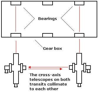
Checking parallelism of bearings in a gearbox is also a simple task using optical equipment. In this example, a 76-RH transit is used to establish the centerline of the first pair of bearings (at left in illustration). By using "bore targets" or some other appropriate targeting, the line of sight of this transit's main telescope is positioned directly on a line between the two bearing centerlines. Then, a second 76-RH is roughly positioned so that it points down the centerline of a second pair of bearings. The reticle in the cross-axis telescope of the first 76-RH is illuminated, and the cross-axis telescope on the second transit is bought into collimation with the first. This makes the main telescopes of both instruments precisely parallel, and the second (or subsequent) pairs of bearings can be evaluated for parallelism to the first.
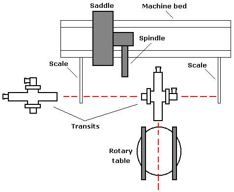
Evaluating and aligning machine tool components
Many of the various capabilities of Optical Tooling come into play when evaluating machine tool components. Testing for straightness, level, squareness, parallelism, colinearity - all can be important depending upon what machine is being tested. In the illustration, which shows a view from above, the transit at left establishes a reference line of sight using scales mounted horizontally on the machine bed ways. This instrument "bucks in" to the two scales (i.e., is oriented such that it reads the same position on each scale). This indicates that the line of sight has been established parallel to the machine ways. Then, another transit (center of picture) turns a precise right angle using the first instrument's reference line, and evaluates the orientation of the ways on the rotary table. Using this basic scheme, a number of different machine tool parameters may be evaluated (straightness of ways in two directions, orientation of spindle, travel of spindle, cross ways on saddle, movement of saddle, etc.)